Self-Balancing Robot Complete Guide
What this project includes:
This project walks you through building a two-wheeled self-balancing robot from the ground up. Along the way, you’ll learn how to use inertia (motion) sensors, program embedded systems, and drive motors. You’ll get hands on experience with IMU’s, PID control, and real-time feedback loops, the same ideas used in drones, Segways and robotics research.
Once you’ve mastered the basics, you can take the project to the next level: add Bluetooth control, build your own PCB, design a custom chassis or even experiment with more advanced control methods. This project gives a solid foundation to explore robotics at a much deeper level.
You’ll build a self-balancing robot that stands upright on its own using real-time sensor feedback and a control loop running on a microcontroller.
Video
Want a quick, visual explanation of how it works? The YouTube video breaks it down in seconds. Including the theory behind the balancing and troubleshooting. Any questions are welcome in the comments.

1. Required hardware
(click on each section for more information and alternatives):
1.1 Components:
- 1x ESP-32 or similar
- 1x L298N motor driver
- 1x 7.4v 2s battery pack
- 1x MPU-6050 – throughout the guide we will call this the IMU (inertial measurement unit)
- 2x 5v DC gear motors (with wheels)
- Jumper wires (lots)
- 2x 0.96″ OLED displays
- 1x Perfboard (or any other connection medium)
1.2 Fasteners:
- 4x ~30mm M3 bolts + nuts (for motors)
- 8-10x ~10-15mm M3 bolts + nuts (for attaching components)
- 12x ~15mm M3 self-tapping wood screws (for attaching 3D printed parts)
1.3 Equipment:
- 4x ~30mm M3 bolts + nuts (for motors)
- 8-10x ~10-15mm M3 bolts + nuts (for attaching components)
- 12x ~15mm M3 self-tapping wood screws (for attaching 3D printed parts)
2. Download the project files
We have provided all of the project files in one organised .ZIP file.
Download the correct file corresponding to your use of OLED’s
Download the correct file set variant:
Extract this file somewhere sensible on your computer. We will reference it throughout the guide.
3. Testing the circuit
Before we begin to build anything, It is always a good idea to test the electronics beforehand. This is where a breadboard can be useful. You should build a circuit according to one of the schematics and instruction sets bellow, on a breadboard or any other temporary connection medium. Insure that you select the correct wiring diagram for whether you want to use OLED’s or not.
Wiring schematic and instructions – WITH OLED’s
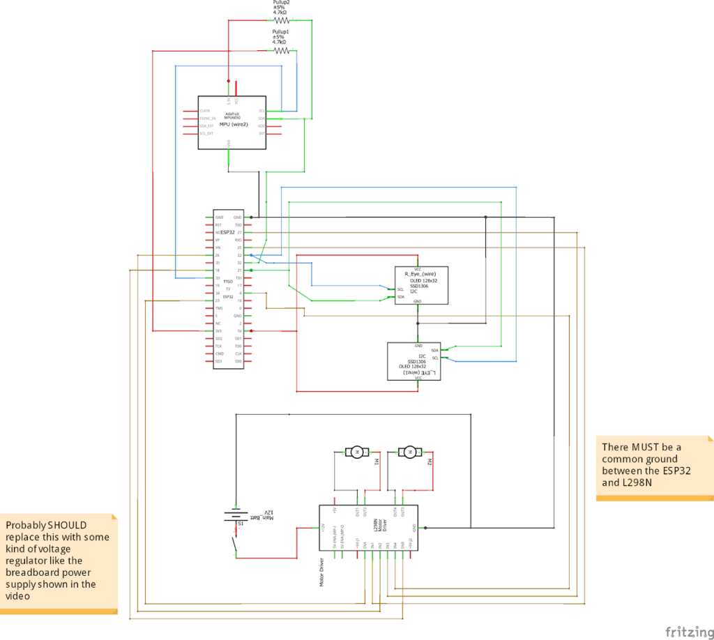
This wiring schematic outlines the connections that must be made between components. This schematic is for use WITH OLED’s. Please ensure you upload the correct code.
Important information:
Both the OLED’s and MPU-6050 will communicate via an I²C connection protocol, this helps reduce wiring complexity but creates a few issues when processing data. Our main issue is that the ESP-32 needs to be able to communicate over 30 frames per second to multiple OLED displays while simultaneously reading the tilt angle from the IMU over 1000 times a second.
On a standard, single-bus I²C setup all of this traffic would share the same physical wire connections. In practice, we found that combining these components together introduced huge amounts of latency causing the OLED’s to become de-synchronised and uneven; the IMU readings inconsistent; and jittery robot balancing.
To solve these issues, we use a multi-bus I²C setup operating simultaneously (something many Arduinos do not support). We also run both OLED displays on the same address so the ESP-32 treats them as one component.
One drawback of this system is that we need to manually solder pullup 4.7kΩ resistors to the MPU-6050 bridging the SCL and SDA lines with VCC.
Wiring schematic and instructions – WITHOUT OLED’s
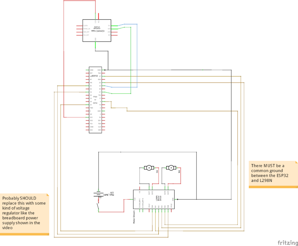
This wiring schematic outlines the connections that must be made between components. This schematic is for use WITHOUT OLED’s. Please ensure you upload the correct code.
3.1 Testing the circuit
Inside the project file you downloaded earlier you should see a “Without web server” folder. Inside that folder you will find the folder containing the correct sketch for your OLED variant.
It should be labelled either:
Code_NOwebserver_NOoleds or Code_NOwebserver_WITHoleds
you should then upload that code to your ESP-32.
You will also need to download the following library’s using the Arduino IDE built-in library manager:
If your using OLED’s you will also need:
These can all be downloaded from the library manager menu in Arduino IDE, but I have provided links to the corresponding GitHub pages.
Also note, if you ARE using Oleds – download the RoboEyes library. It’s a free, open‑source library for OLED‑based robot eye animations and is essential for this project – you can’t get this one from the library manager.
if your not using OLEDs then you don’t need to worry about this
You should expect the motors to spin into action and change speed/direction as you rotate the IMU. If you are using OLED’s you should also expect both OLED’s to display one eye.
If you run into any issues or something doesn’t work, please leave a comment on the respective YouTube video and we will be happy to help you out in a timely manner.
4. Printing the chassis
Next, we need a chassis (frame) for our robot. You will need to 3D print the required quantity of each part
The project file you download earlier should contain a “3D Print files” folder. Within this folder, you should see the following:
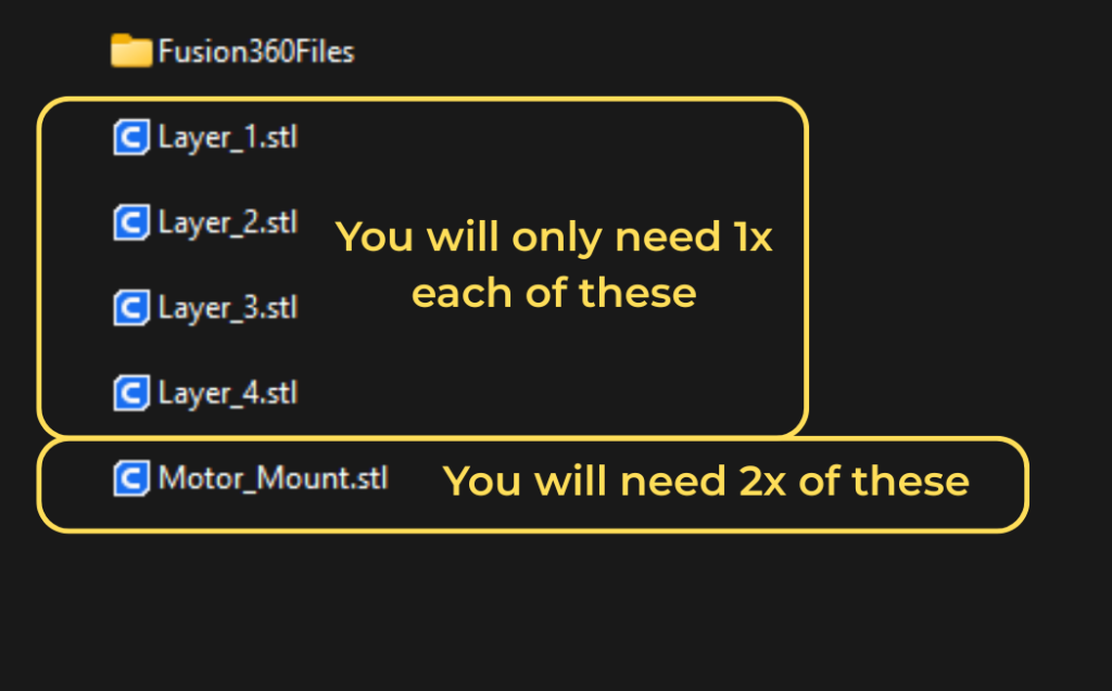
You will need 1x:
- – Layer_1.stl
- – Layer_2.stl
- – Layer_3.stl
- – Layer_4.stl
You will need 2x:
- – Motor_Mount.stl
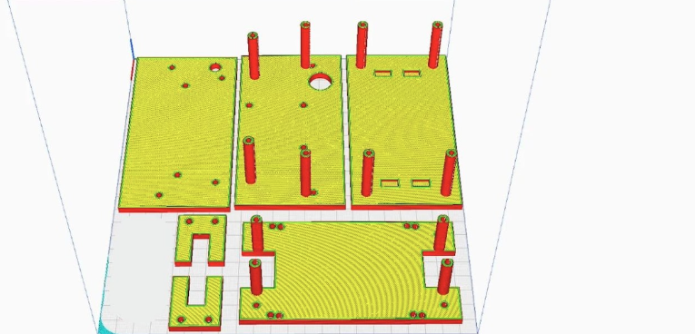
The print settings don’t particularly matter for this build but this is what should be used:
- Support: NO supports
- Infill: 20% gyroid
- Walls: 3 walls
- Layer height <0.2mm
5. Assembly
This is the fun part, we will now construct our robot, it’s pretty simple and self-explanatory but this guide will take you through the process

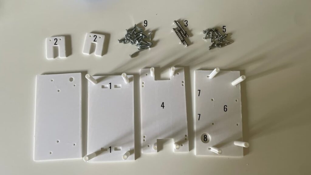
You should now gather all of the 3D printed parts, M3 nuts and bolts, M3 self-tapping screws.
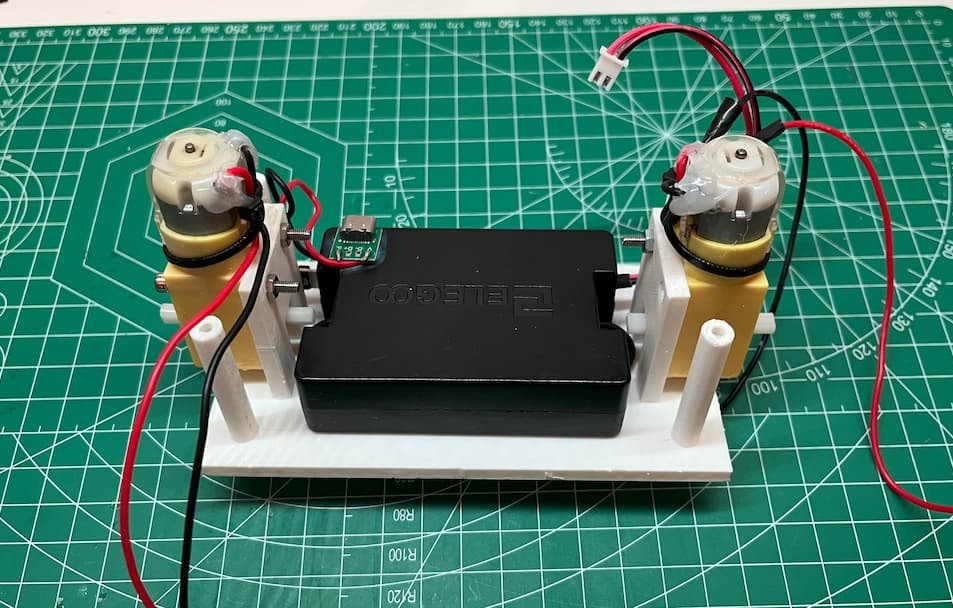
5.1 Mounting the motors
- 1. Add superglue into the rectangular divots on the bottom plate (1)
- 2. Press the motor mounts (2) into place (I needed a hammer).
- 3. Use ~30mm M3 bolts (3) to secure the motors
- 4. Mount your battery in the centre – either with screws or glue.
5.2 Logic board
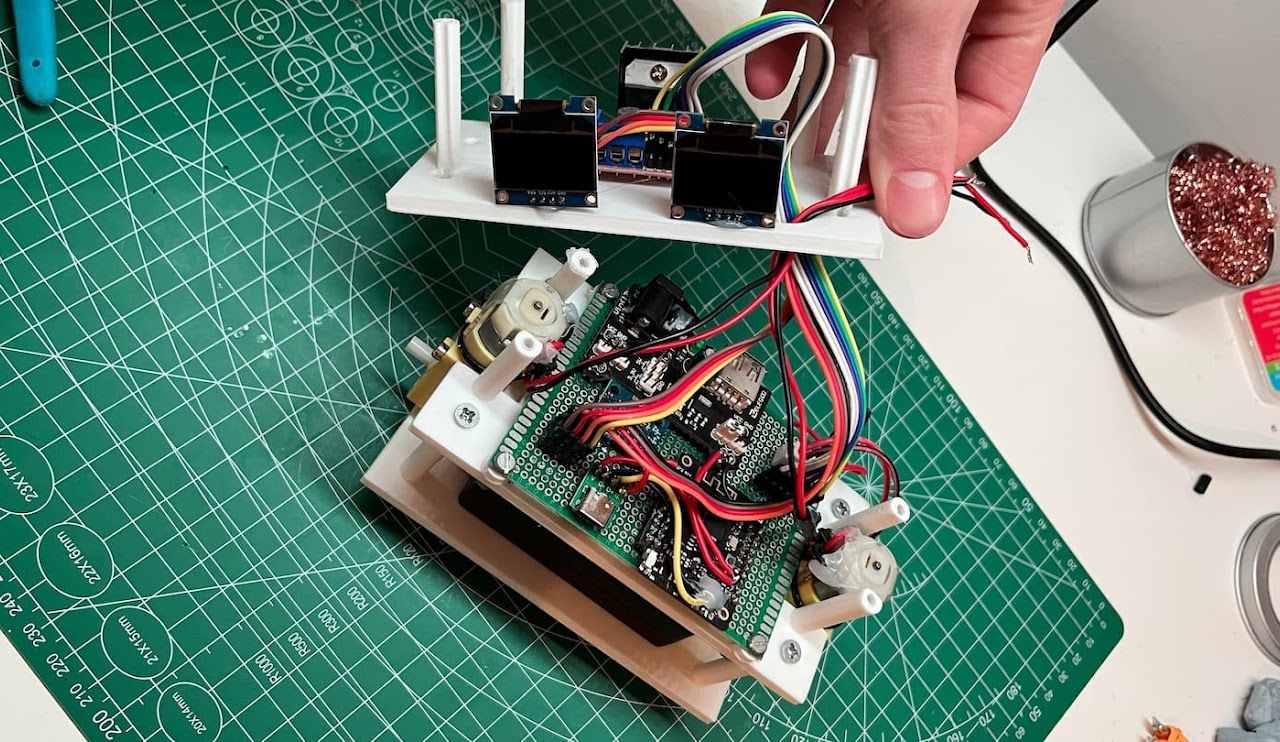
Next, make the main logic board for the robot. According to the correct schematic for your version (refer to section 2). You must leave connections for the L298N and OLEDs as empty pin headers so I could attach jumper wires later. When laying our your logic board, ensure the ESP-32’s USB port is accessible – we will need it later.
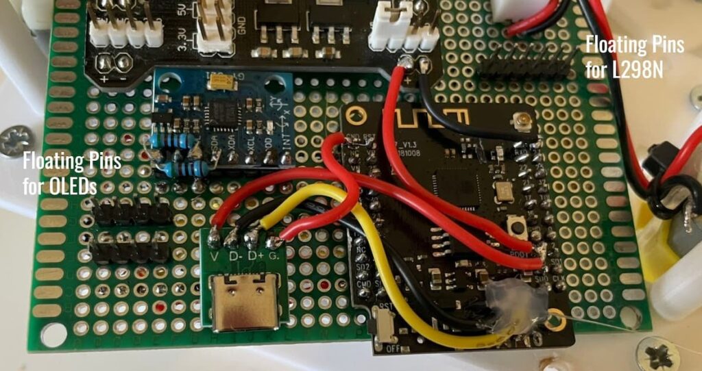
Here’s how mine looked. I used a 70mmx90mm perfboard.
(ignore the extra cables and USB‑C port — I broke the one on the ESP32)
I also used a TTGO T7 esp32 which is why it looks different, this was purely because I had it laying around. But the connections remain the same.
5.3 Power supply
Next, make the main logic board for the robot. According to the correct schematic for your version (refer to section 2). You must leave connections for the L298N and OLEDs as empty pin headers so I could attach jumper wires later
I also used a separate breadboard power supply
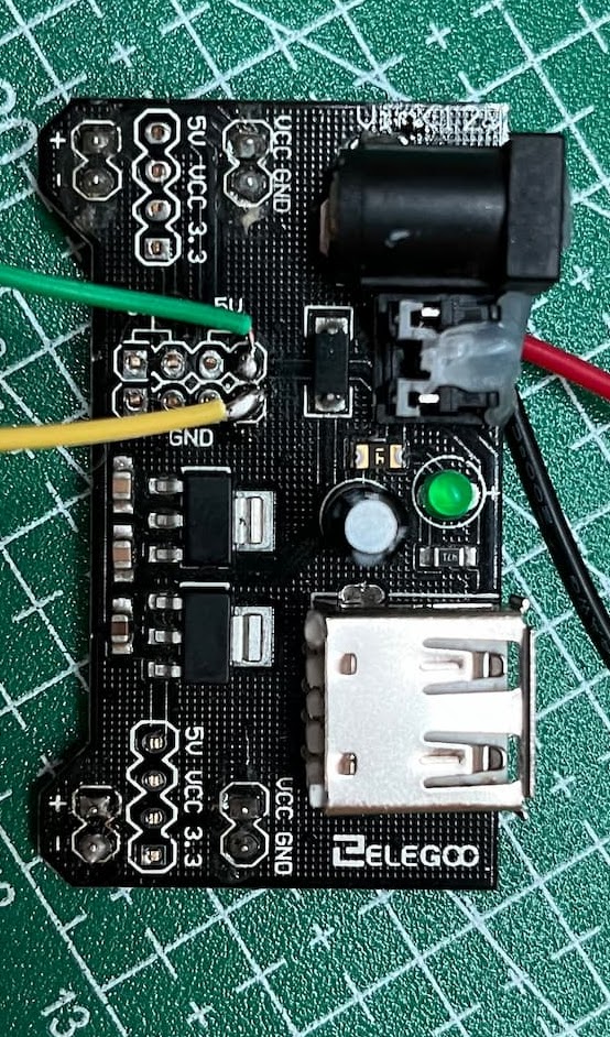
Mines a bit mangled, but if you google “breadboard power supply” then something similar will come up, in the schematics I use the 5V pin on the L298N to power the ESP-32, which would be fine but to quote ChatGPT “Short answer: don’t—at least not if you care about reliability.” (classic Ai response). Because it apparently is noisy and cannot provide enough current, especially during WI-FI bursts. I had this laying around so I went with it. You could replace this with any kind of buck voltage converter or risk it with the L298N. Do your own reasearch.
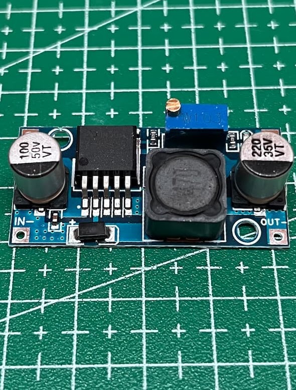
You could alternatively use something like this “HW-4411 DC-DC”
5.4 The Motor Driver
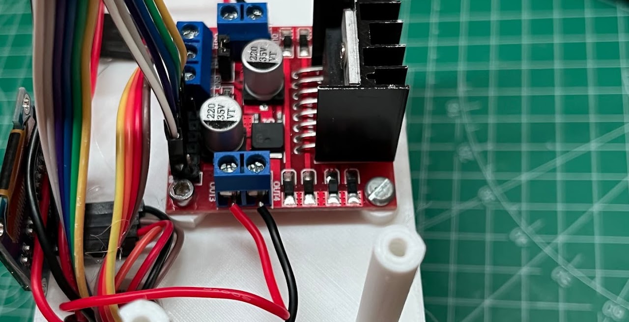
Attach the L298N to the correct plate (6) in the orientation shown using the shorter M3 screws. Add jumper wires and route them through the hole. If using OLEDs, glue them to the front using hot glue (7) and route their wires through the cable hole (8).
This image is repeated for your reference.
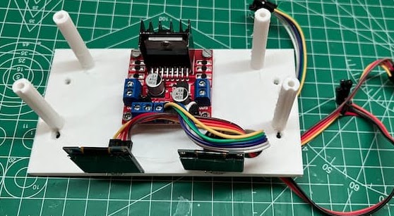
Here is how it should look. You should ensure the correct orientation. (Wire routing hole is in the bottom-right of the image). All wires can then run through the hole.
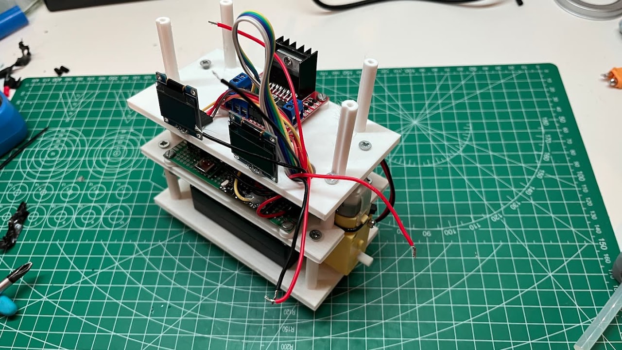
5.5 Final assembly
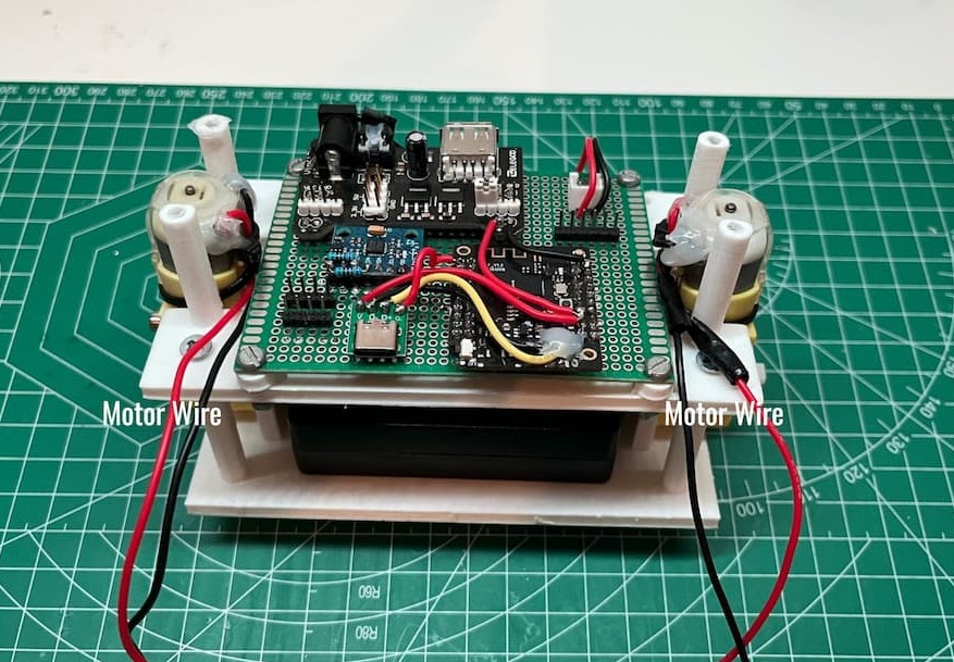
Using the smaller M3 screws and bolts, secure the logic board to the correct plate (4). You should ensure the ESP-32’s USB port is accessible. Then using the M3 self-tapping screws, attach the plate with the logic board to the bottom plate with the battery and motors. Make sure the motor wires are accessible like in the image. Now is also a good time to connect the battery leads to your logic board. I have added a JCT connector to the battery leads and logic board, but direct solder would be fine.
Connect the OLED and L298N wires to the logic board through the cable routing hole. Route the wires from the motors up to the L298N through the routing hole and do the same for power.
Using the self-tapping M3 screws, attach the layers together.
Connect the power and motor wires to the L298N’s screw point terminals.
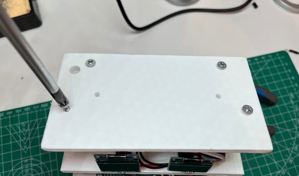
Finally screw on the top plate with the self-tapping screws.
Now you’ve build your robot!
Don’t worry if it doesn’t balance at the moment, we’re going to get to that
6. PID Tuning
Now, we need to tune the PID values for the robot – this part is slightly less fun.
6.1 Upload the new code
Now you must upload the web-server enabled version of your code. Inside of the file you downloaded earlier there should be a folder labelled “With web server”.
Inside that folder, there should be a folder containing a sketch of your OLED variant. It should be called either of the following:
Code_WITHwebserver_WITHoleds or Code_WITHwebserver_NOoleds
Upload the correct variant to your ESP32 – ensure you have the correct library’s installed (note “3.1 – uploading the code“).
6.2 Check motor direction
Now you can power on your robot. We need to identify whether the motors are spinning in the correct direction or not. To do this you should just try and keep the robot balanced upright; if it is just slamming straight into the ground or doing other strange stuff then your motors are going the wrong direction – it will be fairly obvious.
To reverse the motor direction, you have two options, either:
Reverses the direction in which the respective motor wires are connected to the L298N (note “5.5 – final assembly):
Reverse the two red and black wires towards the bottom of the image in the L298N screw point terminals. If your unlucky, both motors may be going opposite directions, but it should be fairly obvious to work out after all there is only 16 combinations and it’ll be obvious when it’s correct.
Or, if both of your motors are spinning the same direction; just incorrect. Then you can reverse it in code:
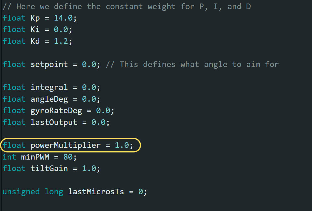
Both code variants will contain this block of code. If you change the value of the “powerMultiplier” from 1.0 to -1.0 then both motors directions will reverse.
This is more convenient however you cannot control individual motor directions in the code.
6.3 Tune the robot
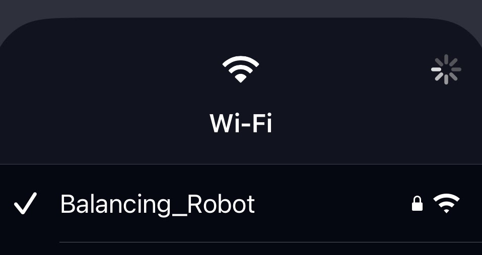
Connect to this network using the passphrase “12345678” you can change this in the code if necessary.
In your browser, open:
this will load the tuning interface. If this link doesn’t connect anywhere make sure your device is connected to the Balancing_Robot WIFI network
This interface allows for fast, real-time tuning and means we don’t have to upload the code every time we want to tweak a value. IMPORTANT: when the robot looses power, it will forget all of your PID tuning hard work so it is imperative that you either write down or screenshot important checkpoints/values that are working for you to return too and if you ever wish to return to defaults; just restart the robot.
Our robot uses a PID control loop. This is a simple yet affective method for achieving a desired equilibrium point. The downside is each of the three sections requires individual tuning.
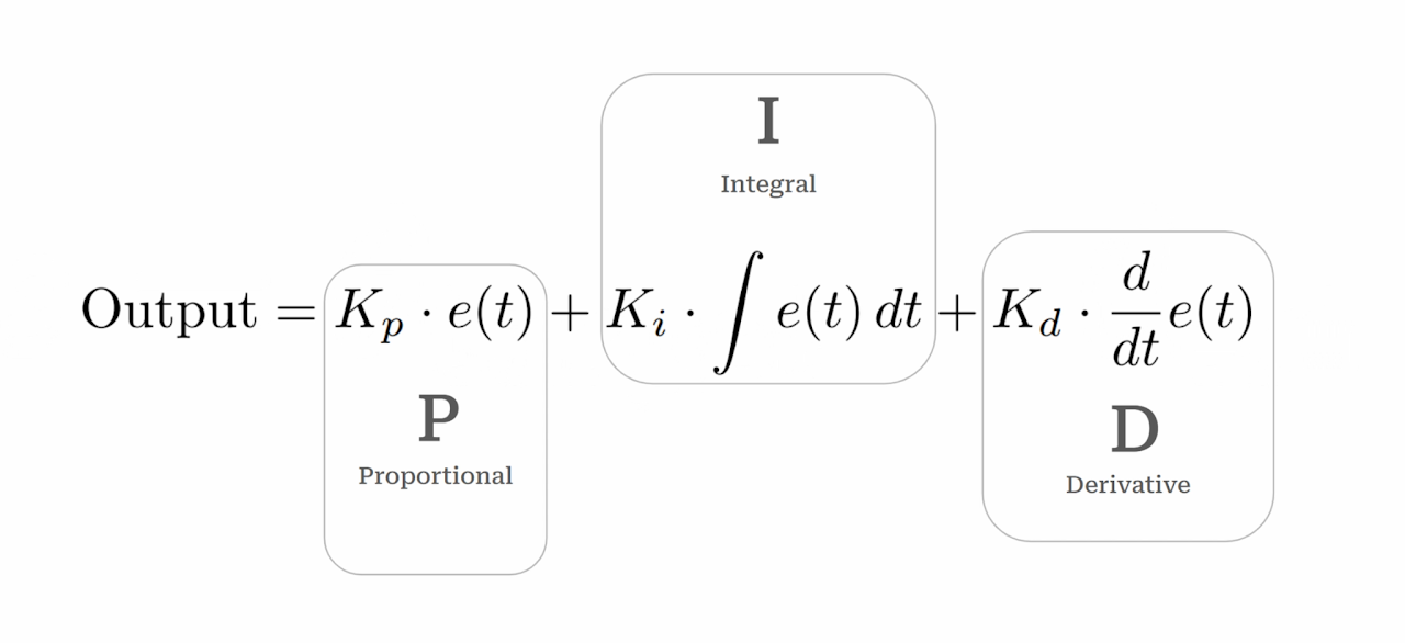
For more information on which each section does, how it works and how we implement it into the robot, check the YouTube guide. (top of the page)
In short:
- Too much P: jittery and twitchy balancing
- Too little P: weak, slow to react and cannot catch itself
- Too much I: big delayed swings, oscillates (vibrates) when falling away
- Too little I: persistent lean, never fully upright
- Too much D: almost nervous-looking, reacts sharply to noise and disturbance
- Too little D: slow, wobble and most importantly – overshoots
Where to begin?
Find equilibrium:
Set the power multiplier to 0, then try and balance the robot at a perfect point without any motor aid. Read this angle from the web page and note it down. Write this value into the “setpoint” section.
Start with only P:
Set:
P = 20, I = 0, D = 0
Increase P until the robot starts oscillating. Then back off slightly – this gives the backbone of the balancing.
Introduce a little D:
Increase D in small increments until the oscillations calm down. Stop as soon as it becomes smooth
Finally, add I:
Increase I in tiny increments just enough so it corrects slow drift. If it starts doing big, delayed swings then reduce I. I is the easiest way to ruin an otherwise good tune.
Other sections:
The landing page will host a variety of other options for tuning and tweaking, if you wish to experiment then feel free but you can safely leave them as-is.
What works for you works:
If your robot doesn’t need any of a certain term (usually I). Then don’t have it!
If your robot doesn’t have PID values at all similar to others. That’s fine!
Your robot will have specific values and tuning that work for you.
SAVE!!:
Once you have found the values. TAKE A PHOTO. Or note them down somewhere. We will need them in the next step.
7. Finishing touches
Now that we have found the optimal PID values it is good practice to hard-code them into the robot so we don’t have to start the webserver every time we turn on the robot.
Go back to the project files you downloaded earlier and open the Inside the “Without web server” folder. Inside that folder you will find the folder containing the correct sketch for your OLED variant.
It should be labelled either:
Code_NOwebserver_NOoleds or Code_NOwebserver_WITHoleds
you should then upload that code to your ESP-32. (exactly like in step 3.1).
At the top of the code you should see this section:
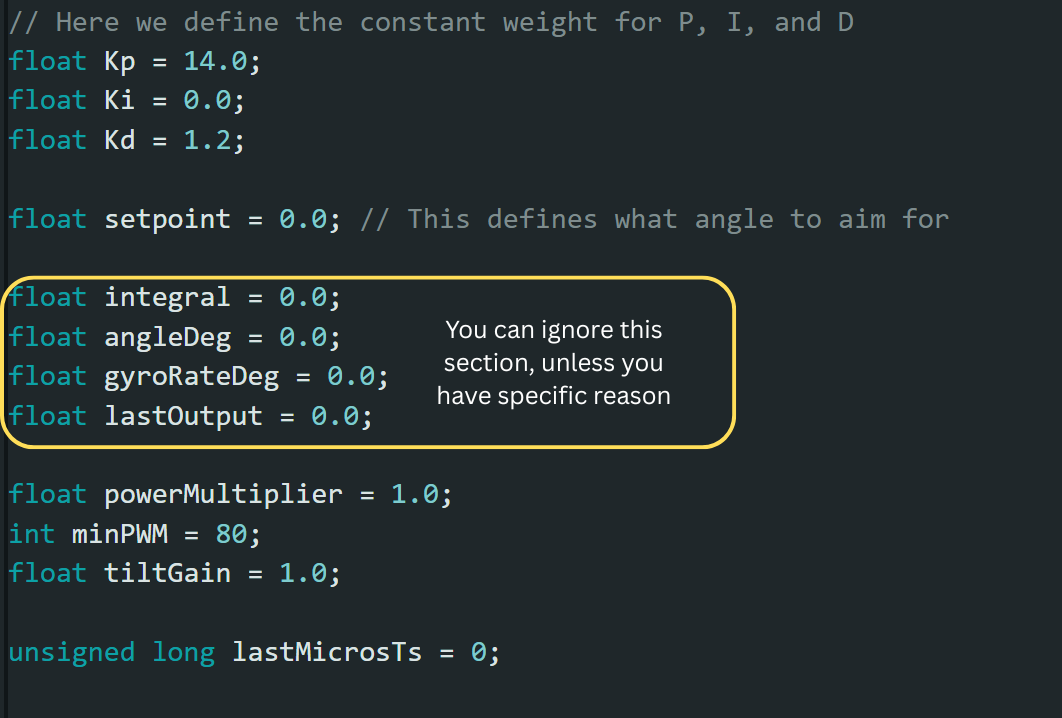
You should copy the values from your record of the webserver page into the corresponding variables in this section of the code.
Hit upload and your done!
Congratulations!
You’ve just built your own self balancing robot FROM SCRATCH. That’s no small achievement and it takes real dedication, critical thinking, problem solving, and a solid grasp of engineering and robotics to get a project like this functioning.
Thank you for spending your time with our guide and choosing to build on of our projects. We hope it taught you something new, challenged you in the right ways and gave you some satisfaction and pride in your project.
Feedback?
At TIEGH, we love to receive user feedback and reviews – it helps us make better projects and tutorials for you.
If you have a moment, a quick review or bit of feedback would mean a lot. It genuinely helps us improve and lets others know whether the project is worth their time.
We’re still a small and fairly new site, so even a single review can make a real difference and jumpstart progress. Only if you want to, of course.